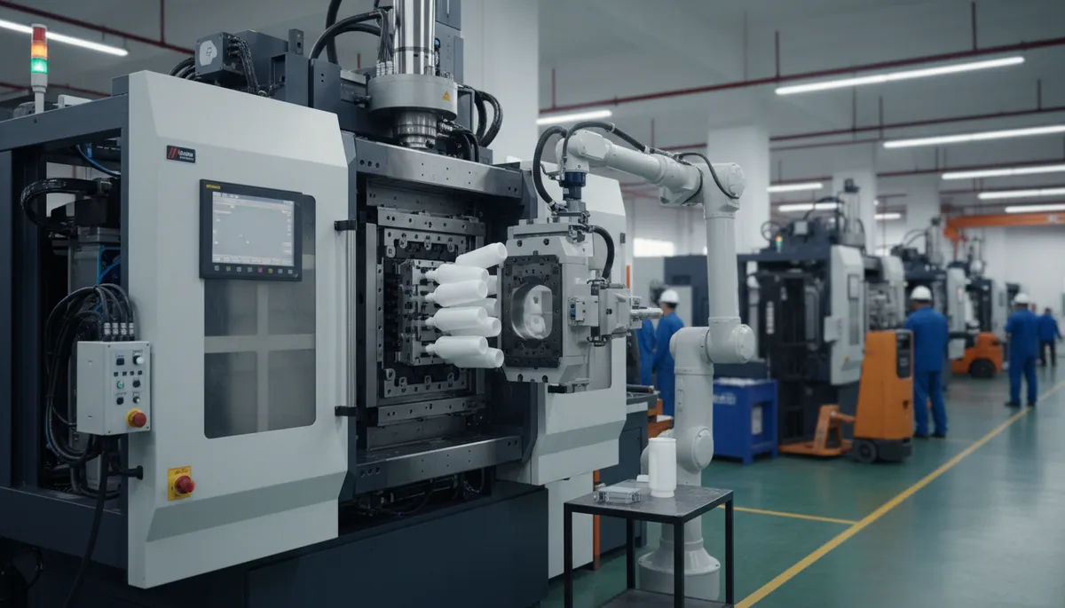
An OEM injection mold supplier manages a custom molding project through controlled engineering stages: requirement review, DFM, material confirmation, mold design, machining, sampling, dimensional verification, process qualification, and production release. A typical tool may contain 50–300 machined components, while part tolerances can reach ±0.05 mm where geometry and resin permit. Multi-cavity molds may produce 4, 8, 16, or more parts per cycle. The supplier records injection pressure, melt temperature, mold temperature, packing time, cooling time, and cavity results during trials. Production approval should depend on repeatable measurements, not a single acceptable sample.
The work normally starts with the customer's 3D CAD file, 2D drawing, resin specification, expected annual volume, cosmetic requirements, and assembly information. Before steel is ordered, the supplier checks wall thickness, ribs, bosses, draft, undercuts, parting lines, shutoffs, ejector locations, gate positions, and dimensions that affect fit. ISO 20457:2026, published in August 2026, covers geometrical and dimensional tolerances for plastic molded parts and recognizes that material behavior, shrinkage, processing conditions, cooling, and warpage can produce larger dimensional variation than metal manufacturing.
That dimensional review leads into DFM because a drawing tolerance cannot be evaluated separately from the molded geometry. A 2.0 mm nominal wall next to a 5.0 mm boss base can cool at a different rate, increasing the likelihood of sink or local distortion. A designer may also request ±0.05 mm on a feature located far from the gate, although resin shrinkage, fiber orientation, and long flow length may make that requirement expensive to maintain across thousands of cycles.
A useful DFM report does not say that a feature is “difficult to mold.” It identifies the feature, gives its dimensions, shows the affected mold area, explains the expected molding result, and proposes a measurable revision.
Draft receives the same treatment. A smooth vertical wall may release with a relatively small angle, while a textured surface normally needs more clearance because the plastic must separate from the texture during ejection. If a 40 mm deep wall has insufficient draft, drag marks and higher ejection force can appear even when the first 10 samples look acceptable. The supplier therefore reviews release conditions before determining slider, lifter, and ejector layouts.
Material information then becomes part of the tool design rather than a purchasing detail. PP, ABS, PC, POM, PA66, PBT, PPS, and glass-filled engineering resins do not shrink, flow, cool, or wear tooling in the same manner. A resin containing 30% glass fiber can create directional shrinkage and greater abrasive wear than an unfilled grade, so gate geometry, steel selection, cavity surface treatment, and replaceable inserts may need to change before machining begins.
The supplier can organize those early inputs in a compact engineering record:
| Item | Typical project information | Supplier response |
|---|---|---|
| Annual demand | 20,000–2,000,000 parts | Select cavity count and mold class |
| Part tolerance | ±0.05 to ±0.20 mm where feasible | Review resin, geometry, datum and process |
| Resin | Unfilled or 10–50% reinforced grade | Set shrinkage allowance and wear strategy |
| Mold life target | 100,000 to 1,000,000+ cycles | Select steel, inserts and maintenance plan |
| Output requirement | Parts per hour or per year | Calculate cavities, cycle time and machine size |
Once those inputs are fixed, filling and cooling behavior can be reviewed before the mold base is released. Simulation can compare several gate locations, pressure distribution, air traps, weld-line position, packing behavior, temperature differences, and expected deformation. ISO 294-1:2017 also emphasizes controlled reporting of injection-molding conditions when producing reproducible thermoplastic test specimens, showing why process settings need to be documented rather than left as operator memory.
Gate selection follows the filling study. A single edge gate may work for a small housing, while an 8-cavity medical or electronics component may need a balanced runner or hot-runner arrangement. Moving a gate by 10–20 mm can change flow direction, weld-line position, packing distance, fiber orientation, and visible gate marks. For a cosmetic enclosure, a location that fills easily may still be rejected if the gate vestige remains on a customer-facing surface.
Cooling is reviewed at the same time because molding output depends heavily on heat removal. If a cycle takes 30 seconds and cooling occupies 18 seconds, cooling represents 60% of that cycle. Reducing cooling from 18 to 15 seconds, while maintaining dimensions and ejection stability, can increase hourly machine output without adding another cavity. Channel position, water flow, bubblers, baffles, core cooling, and temperature-controller capacity therefore belong in the mold-design review.
A fast cycle has little commercial use if parts continue shrinking outside tolerance after ejection. Cooling targets have to include dimensional stability, not only machine cycle time.
The approved design is then converted into machined steel. A production mold may contain cavity and core inserts, ejector plates, support plates, guide components, sliders, lifters, wear plates, cooling fittings, sensors, springs, hot-runner hardware, and replaceable pins. A relatively complex tool can contain more than 100 individual components, so the supplier normally controls part numbers, steel grades, heat treatment, machining status, and inspection records before final assembly.
CNC milling handles many open cavity and core surfaces, while sinker EDM is useful for deep ribs, narrow slots, sharp internal details, and locations inaccessible to standard cutters. Wire EDM is often used for accurate profiles and insert components. Machined inserts can be checked before assembly; finding a 0.08 mm machining deviation at that stage is less disruptive than identifying it after a complete T0 molding trial.
Assembly then connects machining accuracy with mechanical movement. Sliders must reach their intended position before injection, lifters must clear molded undercuts during ejection, ejector pins must return fully, and shutoff surfaces must close without producing excessive wear. Cooling circuits are pressure-checked for leaks, while hot-runner tools require verification of heaters, thermocouples, electrical zones, and nozzle locations.
The first molding trial provides operating data rather than a simple pass/fail result. A supplier may mold 30, 50, or more pieces after reaching stable barrel and mold temperatures, depending on part size and project requirements. The technician records fill time, injection velocity, peak pressure, V/P transfer position, holding pressure, holding time, cushion, screw recovery, cooling time, mold temperature, and total cycle time.
Trial parts are then checked for short shots, flash, burn marks, weld lines, sink, jetting, deformation, ejector marks, gate condition, and dimensional deviation. A 32-cavity tool requires more than checking one attractive part: cavity-to-cavity variation has to be reviewed because different runner balance, venting, cooling, or insert dimensions can produce different results within the same molding cycle.
For dimensional approval, the supplier links measurements to drawing characteristics rather than producing an unrelated inspection sheet. A project with 40 drawing dimensions may classify 8–12 as closely controlled because they affect sealing, assembly, alignment, or functional movement. Measurement equipment may include CMMs, optical systems, micrometers, height gauges, pin gauges, thread gauges, or dedicated fixtures.
ISO 20457:2026 places dimensional control in the context of material, part design, tool layout, and processing conditions, so inspection timing also matters. A nylon part containing moisture-sensitive material can change dimensions after molding, while semi-crystalline polymers can continue developing dimensional change during cooling. Customer and supplier therefore need an agreed conditioning time, measurement temperature, datum method, and inspection fixture.
When dimensions miss specification, tool correction should be based on measured direction and amount. If 8 samples from one cavity average 0.10 mm below a required feature size, the engineer first separates tooling error from molding shrinkage and measurement variation. Changing steel before checking process stability can replace one dimensional problem with another.
The next trial should use controlled comparison data. A T1 or T2 report can show the previous result, steel modification, revised process conditions, sample quantity, current dimension, and acceptance status. A documented 30-part study provides more useful production information than one hand-picked sample, especially where several cavities or tight assembly features are involved.
This is where a Precision injection molding supplier is expected to manage the molding process as carefully as mold construction. Once the tool produces acceptable samples, technicians establish a repeatable processing window rather than one narrow machine setting. Barrel temperature, mold temperature, injection speed, transfer point, holding pressure, holding time, back pressure, cushion, and cooling time are recorded for production reference.
A useful qualification run also tests time. A mold operating correctly for 20 cycles may behave differently after 4 hours when mold temperature, vent contamination, resin drying, lubrication, automation, and insert loading have reached normal production conditions. For an 8-cavity mold running a 25-second cycle, one hour represents about 1,152 molded pieces, giving the quality team a much larger sample population than a short tool trial.
Production planning then extends beyond the press. Insert molding may require operators or robots to load metal parts before every cycle; printed parts may need surface preparation; assemblies may require ultrasonic welding, leak testing, screws, heat-staked inserts, or laser marking. If secondary processing adds 12 seconds to a molded component produced every 20 seconds, workstation capacity and staffing have to be calculated before volume production begins.
Changes are handled with the same level of control. If an OEM revises a boss from 6.0 mm to 7.5 mm after T1, the modification can affect the core pin, boss wall thickness, local cooling, sink on the opposite surface, ejector clearance, and filling behavior. The supplier records the revised CAD version, affected mold components, cost, machining work, trial status, and drawing revision so production does not mix two product definitions.
During mass production, inspection frequency can be based on part risk, cavity count, process history, and customer requirements. A 16-cavity tool producing roughly 2,300 parts per hour at a 25-second cycle creates enough output that an unnoticed cavity-specific defect can generate hundreds of nonconforming parts within one shift. Cavity identification, first-piece checks, scheduled measurements, material-lot records, and process parameter records make containment more practical.
Maintenance planning closes the production loop without ending the project record. After 100,000 or 500,000 cycles, ejector pins, sliders, gates, vents, seals, springs, hot-runner components, and cooling channels may require different service intervals depending on resin and mold construction. The supplier can maintain shot counts, cleaning dates, replaced components, repair dimensions, spare inserts, and approved process settings so the next production run starts from controlled manufacturing data rather than operator recollection.